Autonomous Antenna Pattern Aircraft Overview
- BACKGROUND AND GOALS
The AAPM (Autonomous Antenna Pattern Measurement) is an unmanned arial vehicle (UAV) capable of autonomous flight. Its main objective is to calibrate High Frequency radars placed along the coast that help measure ocean currents. For more information please visit:
http://www.ioos.noaa.gov/hfradar/welcome.html
Video Presentation
http://www.youtube.com/watch?v=GWSTOV8eJk0&list=UUb7c0TFdfdltFaoAAk1_2Lw
Project goals for the the development of the AAPM UAV are as follows:
- Establish a low cost solution for antenna pattern measurements.
- Receive a COA from the FAA.
- Establish permissions from other government agencies with restricted airspace involved with HF radar (Pt Mugu and VAFB)
- Promote the use of low cost UAVs in scientific research.
- Design
The final design configuration of the AAPM consists of a power system, propulsion system, autopilot system, communications system, and a signal source.
- Specifications
Table 1. – Frequencies Used
|
Description |
Value |
Frequency |
Source |
|
Communication Link |
3D Robotics Radio 915 MHz |
~915Mhz |
|
|
RC transmitter |
Frsky DJT radio system |
2.4GHz |
http://www.hobbyking.com/hobbyking/store/__14349__frsky_djt_2_4ghz_combo... |
|
Signal Source |
Custom low power transmitter |
13.5, 12.15 MHz |
10 mw power ouput |
- Physical Specifications
Table 2. – Physical Specifications
|
Description |
Value |
|
Total Weight |
6 lbs |
|
Endurance |
50 minutes |
|
Power to Weight Ratio |
73 W/kg |
|
Thrust to Weight Ratio |
.54 : 1 |
|
Optimal flight speed |
11 m/s |
|
Max rate of climb |
6.0 m/s |
|
Static Trust |
1476 g |
|
Propeller RPM |
5655 rpm |
|
Max input power |
200W |
|
Glide ratio |
16:01 |
- Autopilot System
Ardupilot-Mega 2.6+
The Ardupilot Mega (see Figure 1) has been selected to serve as the UAV's autopilot system (shown in Figure 1 below). The Autopilot consist of a main arduino board around an ATMega 1250 processor and an a variety of sensors.
The Arudupilot Mega incorporates the following key features:
- 3-axis gyros (Vibration resistant Invensense Gyros)
- 3-axis accelerometers. (Analogue Devices ADX330 Accelerometer)
- Absolute Bosch pressure sensor and temp for accurate altitude
- Built-in 16MB Data Logger (The Black Box).
- 10Hz GPS module.
- Voltage sensors for battery status.
- 4GB of onboard data logging memory. Missions are automatically data
logged and can be exported to KML
- Built-in hardware failsafe processor, can return-to-launch on radio loss.
- Include relay can trigger any device; can be controlled by mission scripts.
- Airspeed sensor
- Current sensor
Due to the directional nature of the sensors embedded onto the IMU board the autopilot module requires positioning in a specific orientation in order to function correctly.
- uBlox GPS Module
A uBlox GPS expander is used in conjunction with the Ardupilot to provide
precise positional feedback. The GPS expander interfaces with the Ardupilot via
an I2C connector. This module provides and update rate in excess of 10Hz
featuring excellent sensitivity (-164dBm), quick start up time (14 seconds) and a
positional accuracy of <2m.
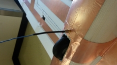
The ceramic patch antenna that the module uses requires satellite LOS to operate.
As the copper antenna shields all signals, the GPS module has
been mounted on the top surface of the UAV with the antenna exposed. This has
been achieved by including a small cut-out in the fuselage section.
- Pitot tube Airspeed Sensor
A pitot static and dynamic airspeed pressure sensor has been integrated to provide
accurate true flight velocity data. As the UAV utilities a pusher prop configuration,
the pitot tubes are mounted out on the wings in order to avoid the prop wash so
that accurate pressure data can be collected. The silicone tubing connecting the
main sensor to the pitot tubes is routed through the front swing-wing bracket, and
through the spar cavity in the wing.
A Freescale Semiconductor MPXV7002 temperature compensated pressure
sensor has been selected. The sensor features state-of-the-art piezoelectric
monolithic silicone pressure sensor providing accurate pressure measurements up
to 7kPa. The sensor links the main Ardupilot board via a standard servo cable
providing 5V of power.
- Power System
Based on the power requirement of the system and the specifications of the motor a suitable ESC was sized based on the maximum current pull of the system including a safety factor. A Castle Creations Phoenix ICE 50 electronic speed controller has been selected for use. This ESC features a 50 amp recommended maximum current and an internal 5v BEC (battery illuminator circuit) that allows all of the on-board systems (including the control servos) to be actuated without the addition of another battery or separate BEC.
- Battery
A Lithium polymer (LiPo) 3S (3 cells in series) 12V 8400MaH battery has been selected for use. Weighting 620 grams in total, the battery accounts for a large percentage of the total avionics system weigh. The battery features a 40C discharge rate, providing adequate power it to the brushless motor and ESC. This high discharge rate is necessary due to the high current draw of the motor under full throttle.
- Communications
3DRadio telemetry
Specifications:
Interchangeable air and ground modules
915 or 433 MHz
Micro-USB port
6-position DF13 connector
100 mW maximum output power (adjustable)
-117 dBm receive sensitivity
Based on HopeRF’s HM-TRP module
RP-SMA connector
2-way full-duplex communication through adaptive TDM
UART interface
Transparent serial link
MAVLink protocol framing
Frequency Hopping Spread Spectrum (FHSS)
Configurable duty cycle
Error correction corrects up to 25% of bit errors
Open-source SIK firmware
Configurable through Mission Planner and APM Planner
Supply voltage: 3.7-6 VDC (from USB or DF13 connector)
Transmit current: 100 mA at 20 dBm
Receive current: 25 mA
Serial interface: 3.3 V UART
26.7 mm x 55.5 mm x 13.3 mm (without antenna)
- RC Control Link – Frsky JRV8 (2.4 GHz)
The Frsky receiver was selected based on a number of considerations. The
primary of which was that the associated transmitter module was able to be fitted into an existing RC transmitter body, and features an SMA antenna connector where most only feature dual non-removable ‘whip style antennas. Secondary to this, the receiver features Advanced Continuous Channel Shifting Technology (ACCST),this allows the receiver and transmitter pair to hop rapidly over 50 channels within the 2400MHz bandwidth. This holds several advantages of this over conventional single frequency receivers in that it is less susceptible to signal interference. This is a major advantage when wanting to operate in urban or semi urban environments where most home wifi networks also utilise the 2.4GHz spectrum. Channel hopping also allows the raises the maximum permissible EIRP as dictated bas dictated by the AMCA from 1W for a fixed frequency transmitter, to 4W for a hopping transmitter.